
How It Works
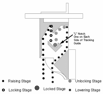
5 Operation StagesThe disconnect assembly operates according to 5 basic stages: Locked, Unlocking, Lowering, Raising, and Locking. The assembly’s design allows the unit to self-align, which enables attached components such as a camera, light fixture, or other device to lock into the same specified position every time the assembly is raised back into the locked stage. In the locked stage, twin tracking support arms with a 600 lbs
(272 kg) 4:1 safety factor sustain the weight of the mounted components without any cable tension or braking device. The principal part responsible for moving the support arms through the 5 stages is the TRACKING GUIDE. This guide is a precision cast series of angular surfaces strategically located to push the support arms in the required direction toward the center “L” notch. The two “L” notches support the entire load of the camera and components when the support arms are in the LOCKED stage. The drawing at right shows the path the support arms take through the tracking guide. Each Symbol represents one of the 5 stages |
|
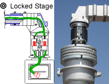
Stage 1: Locked (Latched)
|
The first and most important stage is LOCKED (Latched). Generally, all aspects of the operation of the Disconnect Unit will begin and end in the locked stage. In the locked position, the twin support arms hold all the weight of the surveillance camera. There is no tension on the operating cable, no locking of gears, and no pressure on braking devices to hold the camera secure in its operating position. The electrical and signal contacts are fully engaged and fully insulated and all camera functions are operational when the Disconnect Unit is LOCKED (Latched).
|
|
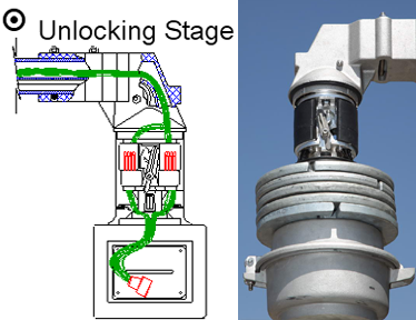
Stage 2: Unlocking
|
The second stage is UNLOCKING. Before lowering the camera, the Disconnect Unit must first be raised approximately ¾ inch. During the slight raising operation, the support arms will be pushed to one side by the tracking guide to clear the support notches. Springs inside the socket half of the connector compress as the Disconnect Unit is raised. Electrical and signal contacts are still engaged during this stage. Each Disconnect Unit has a built-in positive stop that, when reached, will alert the operator to begin lowering the camera. Every time the Disconnect Unit is raised from the “locked” position, the support arms will move and unlock the Disconnect Unit.
|
|
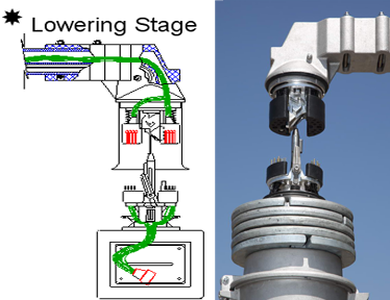
Stage 3: Lowering (Release)
|
With the Disconnect Unit unlocked (released), LOWERING is the next stage. As the camera is lowered, the bottom portion of the Disconnect Unit begins to separate from the tracking guide and the top portion of the Disconnect Unit. Next, the electrical and signal connector disconnects followed by the coming apart of all stabilizing guides. All the weight of the camera and equipment now hangs from the control cable. There are no live electrical contacts to contend with as the camera is lowered to the desired height above the ground for maintenance. Cleaning and repair work can be accomplished at ground level.
|
|
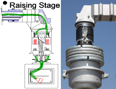
Stage 4: Raising
|
After maintenance to the camera, RAISING is the fourth of the operating stages. During this part, the camera and moveable portion of the Disconnect Unit are raised to the top. As the camera slowly approaches the upper portion of the Disconnect Unit, the control cable initially pre-positions the main guide post in the center hole of the tracking guide. With continued raising, the guide post centers itself in the tracking guide and rotates into its original orientation as the guide post’s cast-in-place key follows the inclined helical surface of the tracking guide. Sustained raising of the camera will engage the next stabilizing key and guide slot of the Disconnect Unit as the support arms toggle through the tracking guide. Electrical and signal pins and sockets of the connector engage as the last step before the lower portion of the Disconnect Unit reaches the very top. Proceed to the final stage: LOCKING.
|
|
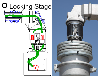
Stage 5: Locking (Latching)
|
The final phase of the 5 operating stages is LOCKING (Latching). During this stage, the camera must be lowered approximately ¾ inch so that the support arms of the lower portion of the Disconnect Unit move toward the center “L” notches of the tracking guide. Springs within the socket half of the connector that were compressed during the final part of the raising stage are now extending and exerting force on the pin half of the connector to assure complete isolation and insulation of the contacts. After the slight lowering operation, the dual support arms are secured in the “L” notches. The Disconnect Unit is now the LOCKED stage. The operating stages 1 through 5 may now be repeated over and over again with the camera returning to its original operating position each time. The operating stages of the Disconnect Unit always begin and end with the Disconnect Unit in the LOCKED (Latched) position.
|
|